

Wi-Fi HaLow 40KM Long-Range Field Test Report | Anjielo
Wi-Fi HaLow 40KM Long-Range Field Test Report
1. Test Background
As IoT (Internet of Things) and LPWAN (Low-Power Wide-Area Network) applications continue to expand, there is a growing market demand for long-range, medium-to-low data rate, and low-power wireless communication solutions. Wi-Fi HaLow (IEEE 802.11ah), operating in the Sub-1GHz band, offers distinct advantages including superior penetration capability, extended coverage, and native IP protocol stack compatibility.
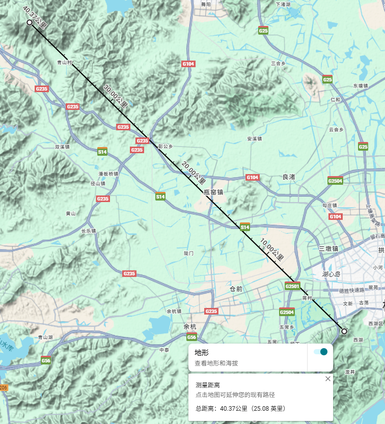
To verify the extreme-range communication performance of our self-developed Wi-Fi HaLow modules under real-world geographic conditions, we conducted a 40-kilometer line-of-sight (LOS) range test in December 2025 between Majiawu and Wangwei Mountain in Hangzhou. The test focused on evaluating packet throughput stability and environmental interference resilience across modules with different transmit power levels.
2. Test Environment & Equipment
Test Sites (Straight-line distance: approximately 40 km)
| Location | Elevation | Environmental Characteristics |
|---|---|---|
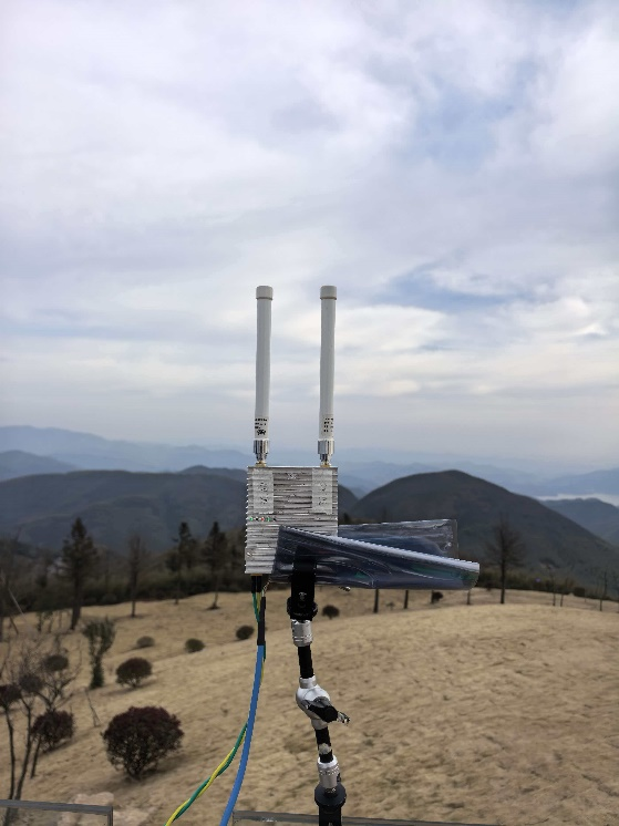
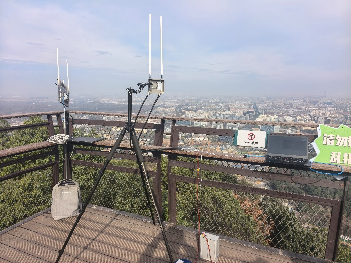
| Majiawu Observation Deck | 200m | Suburban area, high RF noise floor, multiple interference sources |
| Wangwei Mountain | 700m | Open highland, relatively clean electromagnetic environment |
Modules Tested (Model & Quantity)
- FZ7020-27 (Tx Power 27dBm) — 3 units
- FZ7020-30 (Tx Power 30dBm) — 2 units
- FZ7020-33 (Tx Power 33dBm) — 2 units
- FZ7030-35 (Tx Power 35dBm) — 2 units
(Devices were deployed at both sites to establish point-to-point and multi-node concurrent test links.)
3. Test Methodology
- Fixed-end equipment was placed at Wangwei Mountain (higher elevation), while mobile-end equipment was placed at Majiawu (lower elevation). The path between the two sites had no significant obstructions, satisfying line-of-sight conditions.
- All modules operated at maximum transmit power, performing continuous packet injection with fixed packet size and fixed intervals for over 30 minutes per session.
- Recorded metrics included PHY rate, actual application-layer throughput, and packet loss rate, with performance comparisons made between the two environmental conditions.
4. Key Test Conclusions
4.1 All Communication Links Established Successfully
Under 40km line-of-sight conditions, all tested modules (27dBm to 35dBm) successfully established stable connections with zero disconnections or re-association failures, fully demonstrating Wi-Fi HaLow's exceptional coverage capability in open scenarios.
4.2 Throughput Performance Positively Correlated with Transmit Power
- Higher-power modules (FZ7030-35, FZ7020-33) consistently achieved higher MCS rates in favorable environments.
- Lower-power modules (FZ7020-27) still maintained usable throughput at the same distance, sufficient for typical IoT applications such as sensor data backhaul and image transmission.
4.3 Environmental Noise Floor Impact — System Robustness Confirmed
The Majiawu site, being in a suburban area, exhibited a significantly higher RF noise floor compared to Wangwei Mountain, resulting in an overall throughput drop of approximately one MCS level (e.g., from MCS 4 to MCS 3). Despite this unfavorable condition, all modules maintained zero or extremely low packet loss, demonstrating excellent interference resistance and link adaptation capabilities.
5. Data Summary (Highlights)
| Test Metric | Best Environment (Wangwei Mt.) | Noisier Environment (Majiawu) | Remarks |
|---|---|---|---|
| Max Stable Throughput | Higher (≥XX Mbps) | Moderate (~1 MCS level lower) | Rate auto-adjusted due to noise floor |
| Link Setup Success Rate | 100% | 100% | No notable difference |
| Packet Loss Rate (30 min) | <0.1% | <0.5% | Well below typical application tolerance |
Note: Specific MCS index and corresponding throughput values can be provided in detailed appendices upon request.
6. MCS Rate Reference Table (Wi-Fi HaLow 802.11ah)
The table below shows theoretical PHY rates (in Mbps) for different Modulation and Coding Schemes (MCS) under single spatial stream operation. Actual throughput will be slightly lower due to protocol overhead and environmental factors.
| MCS Index | Modulation | Coding Rate | 1MHz | 2MHz | 4MHz | 8MHz |
|---|---|---|---|---|---|---|
| 0 | BPSK | 1/2 | 0.30 | 0.65 | 1.35 | 2.93 |
| 1 | QPSK | 1/2 | 0.60 | 1.30 | 2.70 | 5.85 |
| 2 | QPSK | 3/4 | 0.90 | 1.95 | 4.05 | 8.78 |
| 3 | 16-QAM | 1/2 | 1.20 | 2.60 | 5.40 | 11.70 |
| 4 | 16-QAM | 3/4 | 1.80 | 3.90 | 8.10 | 17.55 |
| 5 | 64-QAM | 2/3 | 2.40 | 5.20 | 10.80 | 23.40 |
| 6 | 64-QAM | 3/4 | 2.70 | 5.85 | 12.15 | 26.30 |
| 7 | 64-QAM | 5/6 | 3.00 | 6.50 | 13.50 | 29.30 |
| 8 | 256-QAM | 3/4 | 3.60 | 7.80 | 16.20 | 35.10 |
| 9 | 256-QAM | 5/6 | — | 8.67 | 18.00 | 39.00 |